Friday, March 29, 2013

Week 10 : FYP1 Presentation

On 28 March 2013, FYP1 presentation was held in Dewan Gemilang. My assessors for that day were Sir Razif and Sir Azuki, Supposedly, on paper, Miss Norhafiza and Sir Razif were my assessors, but for unknown reason, Miss Norhafiza was replaced by Sir Azuki.

My presentation with Sir Razif went well as he also understand about my project. Same thing cannot be said with Sir Azuki. I think my presentation with him went bad, but i don't know how his point of view.


Picture shown above is the motion detector circuit, which i constructed for FYP1 presentation. Unfortunately, it did not working.

Friday, March 22, 2013

Week 9 : Methodology Part 3 - LED Bulb

Last part of this project is LED bulb. LED will be used, to substitute conventional bulb, which is Sodium-vapor bulb. Sodium-vapor bulb produce yellowish light. LED has many advantages over Sodium-vapor lamp.


Picture above shown comparison between LED light (LEFT) and Sodium-vapor light (RIGHT). The LED light only consume 112W, while Sodium-vapor light consume 250W.

Saturday, March 16, 2013

Week 8 : Methodology Part 2 - Motion Detector

In this project, a motion detector circuit, will be used to detect the presence of the vehicle on the road. If there is a vehicle moving pass the motion detector circuit, it will trip the circuit and lamp will be switch on. The  advantage of this circuit, it will prolong the lifespan of battery and lamp bulb. Imagine there is no vehicle using the road, electricity will be drawn from the battery to power up the lamp throughout the night. Although the electricity is free, which we get from sunlight, but we need to consider the battery and lamp bulb as well.


Picture above is a schematic diagram for infra-red motion detector circuit.

Friday, March 8, 2013

Week 7 : Methodology Part 1 - Charging System

My project will emphasize on 3 important parts, which is charging, motion detector and the lamp itself. Under charging parts, there are solar panel, charging controller and battery. The function of charging controller is to make sure, the battery will not be over-charged, when the battery is full. This is to make the lifespan of the battery longer.


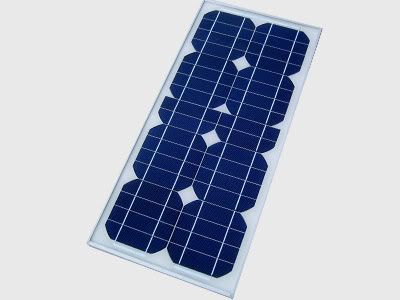
Picture above is the solar panel, which convert sunlight to electricity. When light strikes the solar cell, electrons are knocked loose from the atoms in the semiconductor material. If electrical conductors are attached to the positive and negative sides, forming an electrical circuit, the electrons can be captured in the form of an electric current, which is electricity. the electricity can be used to power a load.


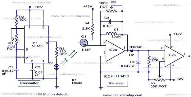
Picture shown above is a schematic diagram of a solar charging controller. The function is to keep battery from overcharging. It regulates the voltage and current coming from the solar panels going to the battery. Most 12V panels, put out about 16-20V, so if there is no regulation, the battery will be damaged from overcharging. Most battery need around 14V to 14.5V to get fully charged.


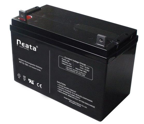
Picture shown above is a special battery for solar, which is a deep cycle battery. A deep-cycle battery is a lead-acid battery designed to be regularly deeply discharged using most of its capacity. 


Friday, March 1, 2013

Week 6 : Aim & Objectives


The aim of this project is to design and develop an intelligent solar-powered highway lamp post
The objectives of this project are as follows:
·       To use solar energy as main source
·       To study on the motion detector circuit
·       To investigate the effect of using LED bulb
·       To design, build and test the charging circuit